
Why Split Bolt Connectors Still Matter in Modern Distribution Networks
Updated: August 27, 2026 | Reading time: 8 min
Key takeaways: A split bolt connector is a mechanical clamp that taps or splices two conductors by compressing them between a split body, pressure bar and torqued nut. It is widely used in LV/MV distribution for copper-to-copper, aluminium-to-aluminium and — with a spacer — copper-to-aluminium joints. Proper sizing, torque and anti-oxidant application are critical for long-term reliability.
Every overhead line, substation tap and service entrance depends on one thing: a low-resistance mechanical connection that stays tight for decades. While compression lugs and cable lugs and connectors dominate factory-terminated assemblies, field conditions often demand a connector that can be installed with ordinary hand tools and adjusted without a hydraulic press. That is where split bolt connectors come in.
For utility buyers, contractors and EPC specifiers, split bolt connectors offer a proven way to make taps, splices and joints on LV/MV conductors — from aerial bundled cables to substation grounding grids. This guide explains how they work, how to size them, and how to avoid the installation mistakes that cause overheating, corrosion and premature failure.
Need split bolt connectors for your LV/MV project?
SUNJ manufactures the SUNJ TJ Split Connector for conductor sizes from 16 mm² to 240 mm², with corrosion-resistant bodies and wrench-friendly hex heads.
What Is a Split Bolt Connector?
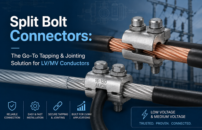
A split bolt connector is a reusable-looking — but single-use-recommended — mechanical splice. It consists of a U-shaped body split down the centre, a pressure bar or spacer, and a threaded nut. Two conductors are laid into the split channel, the pressure bar is seated on top, and the nut is torqued down to create a high-pressure cold-weld between the conductor surfaces.
Unlike crimp lugs, which deform permanently around a conductor, a split bolt relies on clamping force. This makes it ideal for field repairs, emergency restoration and tap connections where exact tooling may not be available. However, that same clamping interface is also its weakest point if the wrong material pairing or torque is used.
The Three Parts of a Reliable Connection
| Component | Typical Material | Function |
|---|---|---|
| Body / saddle | High-strength copper alloy, silicon bronze or tin-plated brass | Holds the conductors and bears the tensile load from tightening |
| Nut / bolt | Copper alloy or stainless steel | Delivers calibrated compressive force via a hex head torque wrench |
| Pressure bar / spacer | Tin-plated copper or bronze | Distributes force evenly and physically separates dissimilar metals |
Sizing a Split Bolt Connector: Run, Tap and Voltage Class
Split bolt connectors are rated by the range of conductors they can safely clamp. The “run” conductor is the main line; the “tap” conductor is the branch. Both must fall within the connector’s approved range. Exceeding the range crushes strands, while undersizing leaves a loose interface that heats under load.
For LV/MV distribution, common practice is to specify connectors tested to IEC 61238-1 for mechanical compression and clamping connectors, or to UL 486A-486B where North American codes apply. Always check the conductor compatibility — Cu-Cu, Al-Al or Cu-Al — because the body material and the need for a spacer depend on it.
SUNJ TJ Split Connector Dimensions
| Conductor size | H (mm) | L (mm) | M (mm) | S (mm) |
|---|---|---|---|---|
| 16 mm² | 5 | 27 | 10.8 | 12 |
| 25 mm² | 7 | 27 | 13 | 14 |
| 35 mm² | 9.8 | 34.5 | 17 | 18 |
| 50–70 mm² | 12.8 | 42 | 22 | 24 |
| 95–120 mm² | 14 | 44.5 | 23.7 | 26 |
| 150–185 mm² | 18 | 55 | 28 | 30 |
| 240 mm² | 19 | 57 | 30 | 32 |
Source: SUNJ TJ Split Connector product page.
Step-by-Step Installation: Torque, Materials and Anti-Oxidant
A correctly specified split bolt connector can still fail if installation is rushed. The most common root causes of failure are under-torquing, mixed metals without a spacer, and skipped surface preparation.
1. Strip and Brush the Conductors
Remove insulation to the length recommended by the connector manufacturer. For aluminium conductors, use a stainless wire brush immediately before insertion to remove the thin oxide layer that forms within seconds.
2. Apply Anti-Oxidant Joint Compound
Any aluminium-to-aluminium or copper-to-aluminium joint needs an anti-oxidant compound. It displaces air and moisture from the interface, preventing high-resistance oxide growth that causes hot spots.
3. Use the Correct Spacer for Mixed Metals
For Cu-Al connections, a tin-plated spacer physically separates the conductors. Without it, galvanic corrosion can degrade the joint in humid or polluted environments. Always verify the connector is dual-rated for the material pair.
4. Torque to the Manufacturer’s Value
Use a calibrated torque wrench, not a spanner by feel. Under-torquing leaves gaps; over-torquing strips threads or crushes strands. Refer to the connector datasheet — values vary by conductor size and bolt diameter.

5. Insulate and Seal the Joint
For energised conductors, insulate the connector to the same dielectric strength as the conductor insulation. The typical sequence is: varnished cambric tape for edge padding, self-fusing rubber tape for the moisture seal, and vinyl electrical tape for abrasion resistance.
Common Pitfalls and How to Avoid Them
Even experienced crews make these mistakes. Avoiding them extends the life of the joint and reduces maintenance call-outs.
| Mistake | Consequence | Best Practice |
|---|---|---|
| Hand-tightening without torque wrench | Loose joint → arcing and overheating | Use a calibrated torque wrench and record the value |
| Skipping anti-oxidant on aluminium | Oxide growth raises contact resistance | Brush and compound every aluminium surface |
| No spacer on Cu-Al joints | Galvanic corrosion and failure | Use a dual-rated connector with a physical spacer |
| Reusing a torqued connector | Compromised thread and clamp force | Treat as single-use after first torque cycle |
| Wrong conductor size range | Crushed strands or loose contact | Verify both run and tap fall inside the datasheet range |
For a deeper look at specification errors, read our article on common mistakes to avoid when buying split lugs.
Not sure which connector fits your conductor combination?
Send us your conductor sizes, voltage class and application. SUNJ’s engineers will recommend the right split bolt connector or parallel groove clamps for the job.
Split Bolt Connectors vs. Other Mechanical Connection Methods
Split bolt connectors are not the only option. Depending on the project, mechanical torque lugs, parallel groove clamps or insulation piercing connectors may be faster or more code-compliant.
| Connection type | Best used when… | Limitations |
|---|---|---|
| Split bolt connector | Field tap or splice on exposed conductors, no press available | Requires manual taping for insulation; torque-critical |
| Mechanical torque lug | Terminating large Cu/Al cables on busbars or equipment | Designed for terminal points, not mid-span taps |
| Parallel groove clamp | Overhead line conductor jointing and repair sleeves | Bulkier; best for line-to-line, not fine taps |
| Insulation piercing connector | Aerial bundled cable (ABC) taps without stripping insulation | Current rating and insulation piercing depth are application-specific |
If your job involves equipment termination rather than mid-span splicing, mechanical torque lugs may be the better fit.
Standards and Certifications That Matter
Split bolt connectors are covered by different standards depending on the market. SUNJ’s quality system is ISO 9001 and ISO 14001 certified, and its cable accessories are tested to IEC 61238, IEC 61284 and NFC 33042. For North American projects, look for UL 486A-486B listing and UL 467 for grounding applications.
- IEC 61238-1 — mechanical compression and clamping connectors for power cables up to 30 kV
- UL 486A-486B — wire connectors and soldering lugs for copper and aluminium conductors
- UL 467 — grounding and bonding equipment fault-current performance
- NFC 33042 / NF C 33-042 — fittings for low-voltage aerial bundled conductors
SUNJ publishes these certifications per product family; always request the test report that matches your project country.
Frequently Asked Questions
What is a split bolt connector used for?
A split bolt connector is used to tap, splice or joint electrical conductors in low- and medium-voltage power networks. Typical applications include overhead line taps, service entrances, substation grounding grids and distribution pillar joints.
How do I size a split bolt connector?
Match both the run and tap conductors to the connector’s approved range. Check the manufacturer’s table for conductor area in mm² or AWG/kcmil, and confirm the rated voltage and short-circuit withstand. The SUNJ TJ Split Connector covers 16 mm² to 240 mm².
Can I connect copper and aluminium conductors with a split bolt connector?
Yes, but only with a connector that is dual-rated (Cu-Al) and includes a spacer that physically separates the two metals. Apply anti-oxidant compound to the aluminium strands before torquing.
What torque should a split bolt connector be tightened to?
Follow the manufacturer’s torque table for the specific model and conductor size. Always use a calibrated torque wrench. Typical values range from 15 N·m for small taps to 75 N·m for large kcmil mains.
Do split bolt connectors need insulation after installation?
Yes, unless the connector is used in a bare grounding array. Energised joints must be insulated to the same dielectric strength as the conductor, typically with rubber splicing tape covered by vinyl electrical tape.
Are split bolt connectors reusable?
Most manufacturers recommend treating them as single-use. Once torqued, the threads and body undergo plastic deformation. Reusing them can reduce clamping force and create a high-resistance joint.
What is the difference between a split bolt connector and a crimp lug?
A split bolt connector is a mechanical clamp that can be installed in the field with a wrench and is suited for taps and splices. A crimp lug is compressed onto the end of a conductor with a hydraulic or mechanical crimp tool and is normally used for equipment termination.
Conclusion
Split bolt connectors remain a practical, field-proven choice for tapping and jointing LV/MV conductors when installation conditions rule out crimping or welding. The key to reliability is matching the connector to the conductor size and material, using the correct spacer for mixed metals, applying anti-oxidant, and torquing to the manufacturer’s specification.
For utility buyers and EPC contractors, specifying connectors from a manufacturer with IEC 61238, UL 486A and ISO 9001 credentials — plus fast regional delivery — keeps projects on schedule and networks resilient.
Related Resources
Source Split Bolt Connectors From SUNJ
IEC-tested split bolt connectors for LV/MV conductors, 16–240 mm², with fast delivery from SUNJ’s Turkey warehouse and direct factory support.
Disclaimer: This article is for general technical guidance. Always reference the latest official IEC, UL and local utility standards before procurement. Product certifications are listed on each SUNJ product page and can be provided on request.