
Introduction
A mechanical cable joint can appear properly assembled from the outside while one conductor has not reached its intended position inside the connector. In a design with a central barrier, two-sided conductor insertion is therefore a measurable installation concern—not simply a question of whether the conductors fit into the barrel.
This guide explains the function of the center stop, the specifications that govern conductor positioning, and the steps engineers should review before rebuilding insulation. SUNJ manufactures BSMB mechanical cable connectors with high-strength, tin-plated aluminum-alloy bodies, shear-head bolts, and prefilled jointing compound in the listed range. View the SUNJ BSMB Mechanical Cable Connector product page for product information and model examples.
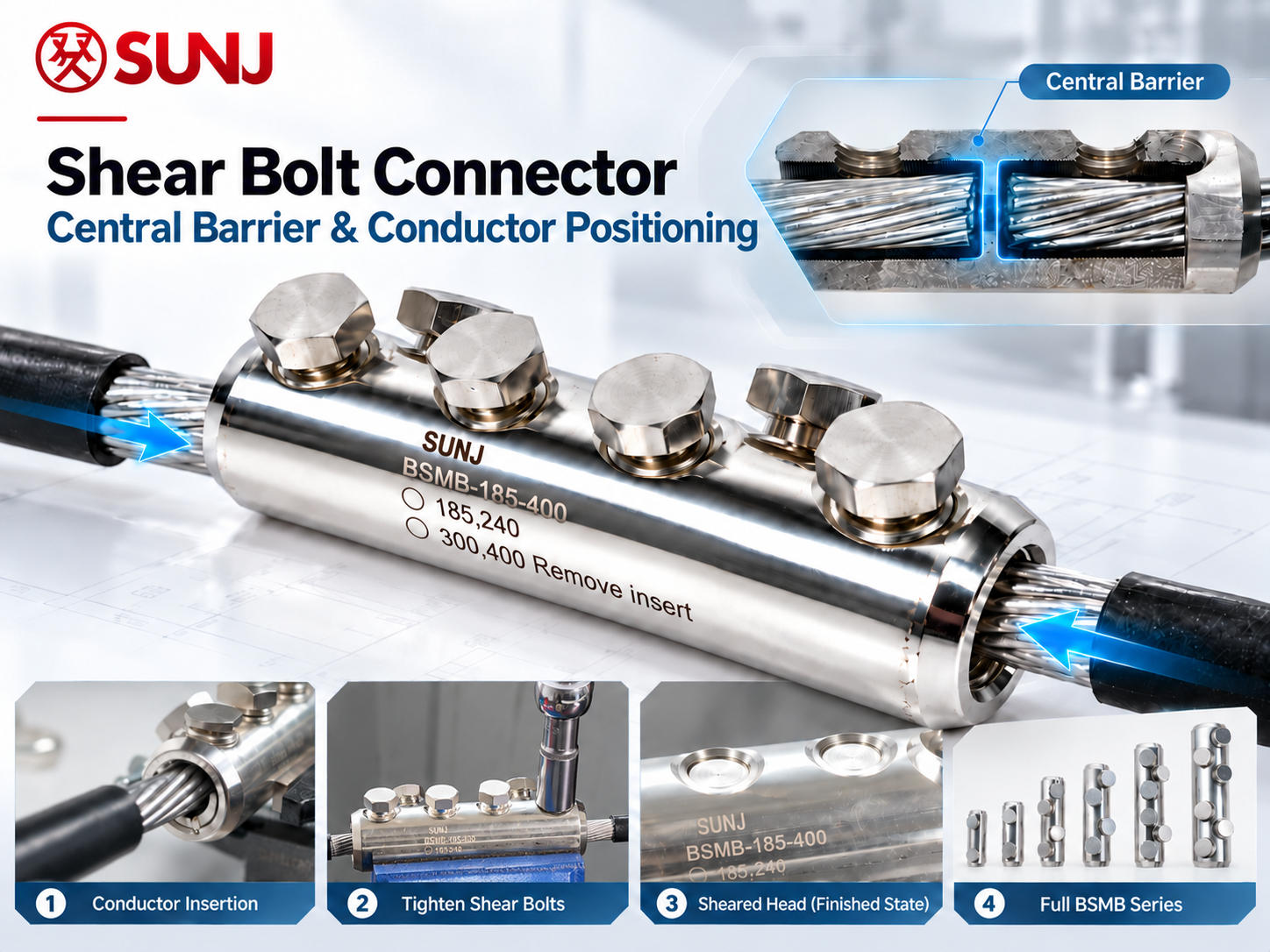
Shear Bolt Connector Central Barrier and Conductor Positioning: What the Center Stop Does
Shear Bolt Connector: Two-Sided Conductor Connection
Unlike a shear bolt lug used for cable termination, a shear bolt connector joins two prepared conductor ends within a straight body. Each conductor enters from an opposite side, and the model-specific bolt arrangement secures the conductors after they have been positioned. The electrical and mechanical result depends on both correct conductor selection and correct insertion.
Shear Bolt Connector: The Barrier as a Positioning Reference
A central barrier, also described as a center block or stop, divides the conductor-entry paths. It provides a physical insertion limit so that one conductor is not pushed through the body toward the opposite side. In normal assembly, each prepared conductor is advanced to its intended stop before the shear bolts are tightened. The barrier helps define conductor position; it does not compensate for an incorrect conductor size, damaged strands, or an unsuitable installation sequence.
The distinction matters for production and field assembly: external symmetry alone cannot establish that both conductor ends are correctly seated inside the barrel. The insertion method, stripping length and pre-tightening checks must follow the applicable product instructions.

Shear Bolt Connector Central Barrier and Conductor Positioning: Model Selection Checks
Shear Bolt Connector Conductor Size Range: Cross-Section and Material
Begin with the nominal cross-sectional area in mm² and the conductor material. Match those values to the model specification rather than selecting solely by the apparent bore diameter. Construction and strand arrangement can also affect preparation and insertion requirements. A connector opening that accepts a cable is not evidence that the cable is within the approved operating range.
Shear Bolt Connector: Barrel Dimensions and Shear-Bolt Arrangement
Next check the body length, entry diameter, relevant dimensional drawing, and number and location of shear bolts. For a cable joint kit, assess the connector’s finished outside profile and the insulation-recovery components that will cover it. SUNJ’s BSMB published specifications identify tin-plated high-strength aluminum-alloy bodies, model-dependent bolt materials, a central block and prefilled jointing compound; the final assembly follows the selected model instructions.
Shear Bolt Connector: BSMB Model Examples
The following examples are taken from the SUNJ BSMB product specifications and illustrate why a product name alone is not enough to select a joint connector.
| BSMB model | Conductor range (mm²) | Shear bolts | Body length L (mm) |
| BSMB-25/95 | 25–95 | 2 | 66 |
| BSMB-35/150 | 35–150 | 2 | 110 |
| BSMB-95/240 | 95–240 | 4 | 125 |
| BSMB-120/300 | 120–300 | 4 | 139 |
For example, BSMB-35/150 and BSMB-95/240 differ in both their listed conductor range and bolt arrangement. The correct selection is the model matching the specified conductors and the cable-joint design—not the model that simply appears closest in size. These values are published model examples; use the current approved datasheet for final technical release.

Shear Bolt Connector Central Barrier and Conductor Positioning: Installation Sequence
Shear Bolt Connector: Prepare Both Conductors
Confirm the model and conductor range first. Prepare both cable ends to the stripping length and strand condition specified by the applicable installation sheet. Keep the strands intact, check the conductor ends for damage, and maintain the cleaning or surface-preparation steps required for the conductor material and joint kit.
Shear Bolt Connector: Insert to the Barrier
Insert each prepared conductor from its assigned side until it reaches the intended center stop. Complete the prescribed positioning check before tightening begins. Do not treat a conductor that only enters the barrel—or two exposed lengths that look visually similar—as proof of correct internal seating.
Shear Bolt Connector Installation Instructions: Tightening Sequence
Use the tool and tightening sequence specified for the selected model. Shear-head bolts are designed to separate at their intended shear point during tightening, but different bolt designs can use different arrangements. Do not transfer a torque value, shear-stage sequence or bolt order from another product. The central barrier and the shear mechanism perform different jobs: positioning occurs before final clamping.
Shear Bolt Connector: Finished Profile and Insulation Recovery
After tightening, inspect the completed connector profile for protrusions, mechanical damage and conformity with the specified joint-kit requirements. Apply the selected heat-shrink or cold-shrink insulation-recovery system according to its instructions. A sound mechanical connection and a suitable external profile are both relevant to the finished joint.

Shear Bolt Connector Central Barrier and Conductor Positioning: Common Installation Errors
Shear Bolt Connector: Physical Fit Without Correct Model Matching
The conductor fits into the hole, so the connector must be suitable. This is the wrong starting point. Conductors must match the declared cross-section and material requirements of the selected connector.
Shear Bolt Connector: Unequal Conductor Insertion
One end is inserted to the center stop while the other end remains short. This can happen when stripping dimensions, positioning or insertion checks are skipped. Confirm seating on both sides before the fastening process removes the opportunity to reposition the conductors.
Shear Bolt Connector: Treating a Sheared Head as the Only Acceptance Check
A detached shear head indicates a designed tightening event, not the completion of every installation check. Conductor compatibility, positioning, applicable tightening order and final joint profile remain separate acceptance points.
Shear Bolt Connector Central Barrier and Conductor Positioning: OEM and Technical Documentation
Shear Bolt Connector Selection Guide: What Technical Teams Should Exchange
For an OEM or replacement-model project, provide the conductor material and cross-section, the intended cable-joint system, target model or dimensional drawing, required quantities, and labeling or packaging requirements. These inputs allow SUNJ to coordinate technical review with manufacturing, sampling and quality-control activities more directly.
Shear Bolt Connector: Sample, Batch and Cable-Joint Compatibility
A practical sample-review package includes a model drawing, conductor-range information, installation sheet and agreed inspection criteria. Review insertion behavior, finished connector dimensions, batch identification, and compatibility with the joint insulation system. SUNJ combines manufacturing and direct export supply to support cable accessory brands, joint-kit producers, importers and distributors with mechanical connectors and OEM cooperation.
FAQ
FAQ1: What is the role of a central barrier in a shear bolt connector?
It acts as a center stop that limits how far conductors can enter from opposite sides. It supports conductor positioning but does not replace the approved conductor range or installation procedure.
FAQ2: Can I choose a connector if both conductors physically fit?
No. Compare the conductor material and mm² range with the exact connector model. Physical fit alone does not establish technical suitability.
FAQ3: Why does SUNJ prefill some BSMB connectors with jointing compound?
The published BSMB range includes prefilled jointing compound as a product feature. Its use should be considered together with the specified conductor preparation and assembly instructions; it is not a substitute for correct insertion and fastening.
FAQ4: Does a sheared bolt head prove both conductors were fully inserted?
No. Bolt shear and conductor positioning are separate checks. Confirm both sides reach their intended position before tightening and inspect the completed joint afterwards.
FAQ5: Which documents are useful for an OEM connector project?
Send the conductor schedule, dimensioned drawing or model reference, cable-joint application, required quantity and any sample, marking or packaging requirements.
Conclusion
The value of a center barrier lies in controlled conductor positioning within a properly selected mechanical cable connector. Reliable assembly starts with the correct conductor range and model geometry, continues with both conductor ends seated at their intended stop, and finishes with model-specific shear-bolt tightening and joint insulation checks.
SUNJ manufactures and supplies shear bolt connectors for cable accessory applications and supports OEM model development and technical coordination. Send your conductor requirements, joint drawings and project details through our contact page to discuss an appropriate connector solution.